Meshing in Topology Optimization
In topology optimization (TO) usually three different meshes are used: stuctured, unstructured and body-fitted meshes.
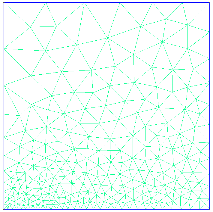
Figure: Structured (left) and unstructured mesh (right).
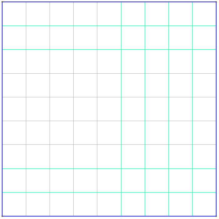
The common choice in TO, a stuctured mesh is a structured grid, usually Cartesian, where the entire design domain is discretized into uniform elements. Besides their implementation simplicity, these meshes open the door to geometric multigrid solvers (GMG) which can increase numerical efficiency of the underlying finite element problem by orders of magnitude and can also make use of details specific to TO to increase efficiency further [14].
Unstructured meshes are built from elements that do not follow a regular grid pattern. Instead of repeating rectangles or cubes, the elements can have varying shapes and sizes—most often triangles in two dimensions or tetrahedra in three dimensions—that are placed in a flexible way to conform to arbitrary geometries. In TO, most the time irregular mehes offer no advantage in most cases and further complicate implementation of methods. Why no advantages? Typically irregular meshes are used in FE to accomodate sections of the geometry that are either very complex or where a high accuracy of the numerical solution is needed. Complex geometries do not exist in TO a-priori as finding the final design is why one does TO in the first place. Physical accuracy is needed in TO everywhere - although some shortcuts are possible here, but more at another time - as otherwise the constrained optimizer will exploit poor numerics to create designs that perform well for the given numerical parameters b ut will perform poor with accurate numerics and thus also in experiments.
A body-fitted mesh is created by discretizing the (final) TO design with an irregular mesh to offer a better geometrical and physical description which may be needed as sanity check on the final TO design or during the TO iteration if accurate description is detrimental (e. g. contact problems) or if the specific TO method (e. g. level set based TO with cut-element methdo) easily allows for the creation of the body-fitting on-the-fly.
Regular Mesh used in topoptlab
In topoptlab, in most cases we use a mesh as displayed in this subsection and
we assume our elements to be in the reference domain spanning [-1,1] in each
spatial dimesion. In 2d the local degrees of freedom in the elements are
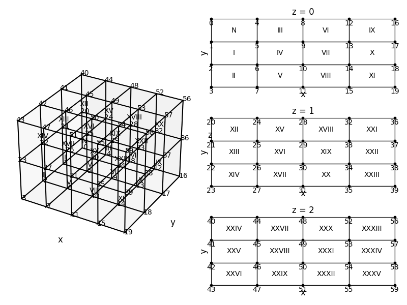
arranged counter-clockwise starting from the node located at (-1,-1). In 3d the
same method is used where we start from node (-1,-1,-1), number all nodes with
\(z=-1\) and then repeat the same for the nodes \(z=1\). This is the same approach
as in the famous 88 line code[9] and its updated version [15]
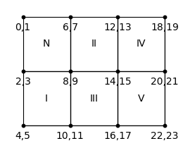
For scalar fields (e. g. temperature) the global degrees of freedom are
enumerated as follows (with elements as roman numbers) in 2D
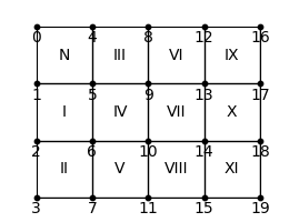
and in 3D
Vector fields in 2D are enumerated as
and in 3D as
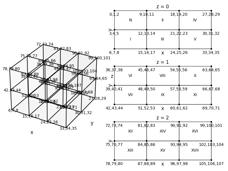
To better view these numberings, you also directly plot them via
topoptlab_mesh.py.