Variable Thickness Sheet
In variable thickness sheets, you optimize 2D geometries in terms of the tickness of each element \(\boldsymbol{t}\). Since for isotropic linear elasticity, the element stiffness matrix \(\boldsymbol{K}_e\) scales like \(\boldsymbol{K}_e \propto E_e t_e\), this is the same as taking the conventional SIMP interpolation for rescaling the materials Young’s modulus \(E_0\) to an effictive Young’s modulus \(E_{eff}\) via
with \(k=1\) instead of usual \(k\approx3\). We perform this optimization for the basic cantilever case of the famous 88 line code case, via these few lines
from topoptlab.topology_optimization import main
from topoptlab.example_bc.lin_elast import cantilever_2d

# The real main driver
if __name__ == "__main__":
    # geometry input parameters
    nelx = 160
    nely = int(5/8 * nelx)
    # volume constraint
    volfrac = 0.4
    # filter radius
    rmin = 3/80 *nelx
    # only set to one for variable thickness sheets. Otherwise k=1 is nonsense!
    penal = 1.0
    # sensitivity filter
    ft = 0
    # display on screen
    display = True
    # export vtk file
    export = True
    # write a log file
    write_log = True
    # run the actual optimization
    main(nelx=nelx, nely=nely,
         volfrac=volfrac,
         penal=penal, rmin=rmin,
         ft=ft, # integer indicating the filter to be used
         filter_mode="matrix", # indicating how filtering is performed
         optimizer="oc", # use optimality criteria method
         bcs=cantilever_2d, # boundary conditions for cantilever in 2d
         output_kw = {"file": "cantilever_2d",
                      "display": display,
                      "export": export,
                      "write_log": write_log,
                      "profile": False,
                      "verbosity": 20,
                      "output_movie": False})
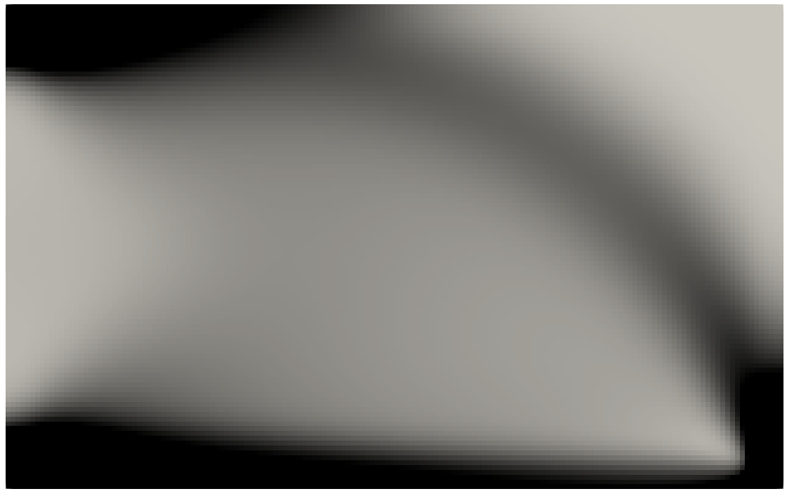
Take the vtk-file “cantilever_2d.vtk” and open it in Paraview. In “Properties”, click on “Coloring” which should have “Solid Color” written right now. Select xPhys instead. To get a different coloring, click “Edit color map”, go directly under the transfer functions to “Select a colormap from default maps” and select “X Ray”. Now you should see
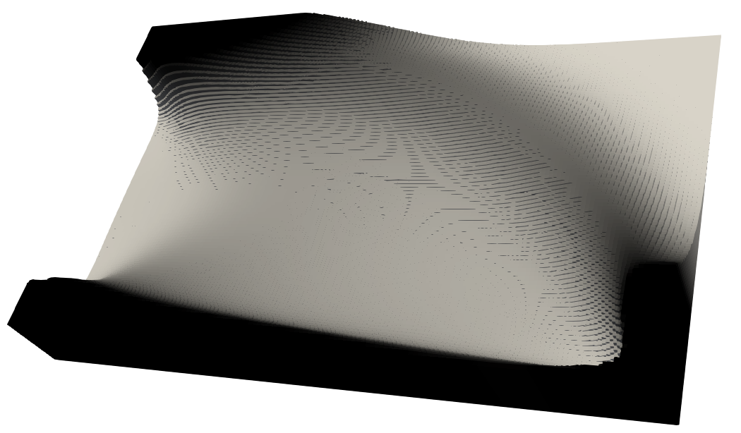
To convert this view to a variable thickness design, go to
filters, choose Extract Surface and after this Linear Cell Extrusion.
Go to the bottom of the Properties of the Linear Cell Extrusion, unselect
“Use Color Palette For Background”, click on Background and choose
white. Now you should see the final design